7 Install components of wiring distribution
The places where the network cables and devices are connected are known as the wiring closets or the telecommunication rooms. The main devices like hubs, routers, servers and switches to name a few are placed in the closet. The components found in a wiring closet are: cross connects, horizontal cables, vertical cables, patch panels, punch down blocks, IDF's, MDF's to specify a few. Dealing with them in detail:
Network Cross Connects: 'Cross Connects' is the term that is used to describe the point where the cables running through the network meet and are connected. Two kinds of cables run through the network:
- The Horizontal cable - connecting the client systems to the network;
- The Vertical Cable - running between floors, connecting different locations on the network.
These wires are collected in the wiring closet and the points where they connect are known as cross connects. There are three types of cross connects:
- The Horizontal Cross Connect- The horizontal cross connect is the meeting point of vertical and horizontal connections. It is used to connect all connecting hardware like patch cables and cords. It serves as the termination point for network horizontal cable.
- The Intermediate Cross Connect- These types of cross connects are used in large networks. It serves as a cross connects between the main and horizontal connects.
- The Vertical Cross- This is also known as the main cross connect. This is the point where outside cables enter for distribution around in the network. Examples of this type of wiring are internet and phone cables.
Horizontal Cabling: The horizontal cables connect the telecommunications room to the end user. It starts from the telecommunications outlet with a RJ-45 connector at the end of the client. It is inclusive of all the cables that start out from telecommunications room towards the horizontal cross connect. It runs within walls and ceilings and is hence also referred to permanent cable. The length of the cable should not ideally be more than 90 meters and patch cables should not be more than 5 meters.
Vertical Cabling: This is also referred to as the backbone cable. It connects telecommunications rooms, server rooms, remote locations, offices. It connects locations which are outside the local LAN. It is used for connections where speed is critical and as a result fiber optic cable and high speed UTP cable is ideally suited.
Patch Panels: A patch panel could be a free standing or a wall mounted unit and has a number of RJ-45 connections on the front. It is a distribution block looking like a hub without the light emitting diodes. It serves as a connection point between hubs, switches, ports to which the ports are connected.
Punch Down Blocks: The punch down blocks came to be used mush before the patch panels. The telephone wires or UTP cables are attached to the punch down block using the punch down tool. A punch down block consists of a series of ICD's (Insulation Displacement Connectors). ICD's are metal tabs and are used for placing the wires. The connector takes the insulation off the wire before it is embedded into it. This works faster than stripping the insulation off the wire and twisting the same around a connection pole. T cable contractor or an administrator may be expected to do this task. There are two main types of punch down blocks:
- Type 66: It is a block that is used for connecting telephone systems and other low speed networks. It serves the same purpose, that is, of embed the wire into metal slots san the insulation. A 66 type punch block has 50 rows of IDC contacts on which 25 pairs are accommodated. This type of block is used for voice communication, but is not very successful as it is not able to deal with cross talk effectively. Though approved for Category 5 cables, its use is limited to 16 MHZ.
- Type 110: This replaced the 66 type block for the reasons of handling higher frequencies and being able to deal with cross talk in a better manner. Unlike the 66 type which allows for only 25 pairs to be placed, the 110 type allows for 25, 50, 100, 200 or 300 wire pairs. It is composed of two parts 110-IC connector, which is used for terminating the wires and the 110 wiring block, for attaching the connectors. It has 110 terminating connectors, one each for every cable that has to be terminated. This type is a wall mounted type with all the 110 connectors visible from the front.
MDF and IDF: Main Distribution Frame and Intermediate Distribution Frame are used to describe the types of wiring closets. The main wiring closet is known as the MDF and it is used for holding routers, wiring, servers, switches and other such network devices. A primary patch panel is a key component of an MDF. Multiple wiring closets are also used by some networks. In such cases the MDF connects to IDF's or the secondary wiring closets. These are connected by a vertical cable. The vertical cable can be of any type UTP, Fiber or Coaxial. The figure given below illustrates the relationship between the MDF and the IDF.
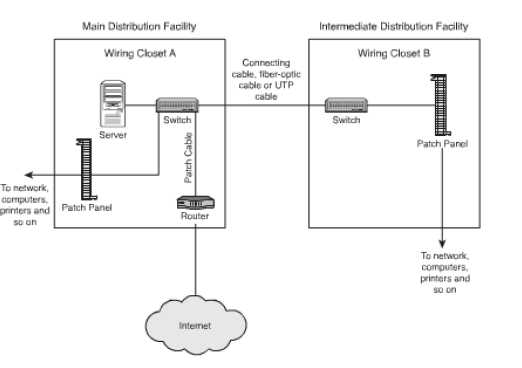
Figure 24: Relationship between MDF and IDF
Demarcation Point: This point is the point of connection between the ISP part of the network and the customer portion. This point is of critical importance for administrators as it distinguishes the part of the network for which the administrator is responsible from the part for which the internet service provider is responsible. In the case of high speed internet, it is ISP's responsibility to support everything from the cable modem to the distribution center. It is the responsibility of the ISP to ensure that the network is flawless up to the demarcation point beyond which the customer is responsible.
Demarcation Extension: As already discussed above the demarcation point is the point where the ISP places its services in your network. The demarcation point may not always be at the best of locations and in case of inconvenient or inappropriate locations demarcation extension may need to be provided. It extends the point to a more functional or a suitable location. Cabling and other infrastructure needs may be an issue for setting up extensions.
Smart Jacks: The hardware devices that are placed at the demarcation point are known as smart jacks. These are also known as NID (Network Interface Device). The main features and the functions of a smart jack are:
- Loopback: This feature is used for testing. It permits remote testing and as a result technicians do not need to be called at the drop of a hat.
- Amplification of Signals: This feature allows for signals to be amplified. This is the same function as that of a repeater in an Ethernet network.
- Protection from Electrical Surges: This device allows protection against electrical surges caused by environmental situations.
- Remote Alarms: Alarms are an integral feature of smart jacks. These alarms help the owner to identify if something is wrong in this system.